How to Read Droplets on Teflon Slides
ane. Introduction
Although known since the studies of Wenzel, and Cassie and Baxter [1,two], the attending towards the theme of superhydrophobicity was steeply renewed when the behavior of the lotus leafage was discovered and correlated with its multiscale structured hydrophobic (hence superhydrophobic) surface [3].
So far, this phenomenon has been investigated mainly for cocky-cleaning applications (textiles, windshields, etc.) [four] or microfluidics (lab on a chip) [5]. Cocky-cleaning applications require both the capability of favoring drop sliding (to comport out dirt particles) and that of repelling impacting water aerosol (so the surface gets speedily rid of the liquid) [half-dozen].
A drop impacting on a superhydrophobic surface volition spread out to a maximum diameter and and so recoil to such an extent that information technology completely rebounds and leaves the solid material. In the past decade, it has been shown that the quasi-elastic bouncing of water drops is a typical characteristic of markedly superhydrohobic surfaces, and measurements of the time the drop remains in contact with the surface has been reported [vii,viii]. Since and so, many works have been published on the ability of superhydrophobic surfaces of promoting billowy of h2o droplets [9,10,11,12,xiii,14].
Simply in the very last years, the skin friction drag reduction potentialities of superhydrophobic surfaces in macrofluidic applications have come under study. Experiments inspired past "water striders"—insects with superhydrophobic legs [15]—have been conducted with small superhydrophobic objects moving horizontally on water surface nether laminar conditions. Important drag reduction (increased speed) results, though with very unlike extent, take been reported in this instance (25%–70%) [16,17]. A reduction of elevate has been observed likewise onto relatively larger ship-shaped objects moving on the h2o surface [18].
On the other hand, when the move is tested underwater (vertical or horizontal direction) the results appear conflicting, since increased [16] and reduced elevate [19,20,21] tin can exist found in literature.
These clues indicate that the elevate reducing performance underwater presents some critical aspects which deserve to be further investigated.
Nether this perspective, the inspiration of the Salvinia molesta leafage—aquatic found capable of retaining air nether h2o amidst the so called "eggbeater trichomes"—may represent an interesting strategy [21,22,23]. All the same, information technology is worth pointing out that such a bio-example works in nature strictly under static conditions and the way it tin can be improved and made suitable for dynamic conditions withal represents an open challenge.
We have previously shown that the Cassie land, characterized by high static contact angle and depression hysteresis under motion (i.eastward., low free energy of adhesion between the solid and water) can be artificially obtained on several kinds of materials. In particular, several plastic materials accept been turned to water repellent with a simple unmarried stride plasma carving process producing uniform expanses of nanometric and size-tunable ripples [24,25].
This process has also been shown to be effective in imparting some other biomimetic functionality (i.e., the low reflectivity of visible and UV lite, according to the moth-middle effect [26]).
Lately we have tested this process on Teflon (polytetrafluoroethylene, PTFE) in guild to exploit the intrinsic hydrophobic properties of this polymer, hence utilizing uncomplicated ablation/roughening processes without the necessity of making coatings. This strategy has been also followed by other authors who have used a method of sandpaper sanding process, which is very inexpensive but less controllable [27].
We take shown that the repulsive properties against impacting water aerosol (i.e., the critical pressure for water penetration) can be enhanced on the plasma modified material [28]. Also, the topographical modification has been shown to be tunable not just in terms of size but also in terms of shape, by ranging from spheres- to filaments-topped structures.
In this piece of work, we move towards an in-water characterization of Teflon objects modified with such a plasma process. Past making a comparative characterization betwixt the untreated polymer and the best performing textured Teflon, we investigate the response in ambient air to impacting water aerosol and, underwater, the advent of trapped air over the surface under static and dynamic conditions. This style we aim at reaching a commencement agreement of the anti-drag potential of this superhydrophobic modification onto simply-shaped three-dimensional (3D) objects in water.
2. Materials and Methods
2.1. Teflon Surface Modification
Teflon 0.5 mm thick sheets, purchased from Goodfellow (Huntingdon, Great britain), were cutting in 15 mm × 40 mm pieces. The Teflon spheres (solid spheres, 19 mm diameter, 2200 kg/m3 density) were purchased from New Ball SAS (Milan, Italy). Both samples types were sonicated in isopropyl alcohol and dried earlier processing.
The plasma micro/nanotexturing process was carried out in a home-made capacitively coupled reactor (Figure 1) with two parallel stainless steel electrodes having a gap of 4 cm, the upper i continued to the ground and the lower one connected to a radio-frequency (RF, 13.56 MHz; Caesar Dressler, Metzingen, Germany) ability supply via a matching network. Both electrodes had a 314 cm2 surface surface area and were included in a stainless steel vacuum chamber evacuated with a rotative-turbomolecular pumping arrangement (base pressure 10−iii Pa; Leybold GmbH, Cologne, Federal republic of germany). Samples were located on the bottom electrode (the spheres were positioned within small steel rings and turned upside downward at half-time process). Oxygen was used every bit feed gas. The gas flow rate was controlled by means of electronic gas flow meters, and vacuum measured with a Baratron gauge (MKS Instruments, Andover, MA, USA). Samples for this work were prepared feeding the bedchamber with 30 sccm of oxygen at 13 Pa, at a power of 200 W and a elapsing of 10 min.
2.2. Topographical and Chemical Characterization
The surface morphology of Teflon samples was investigated past means of field emission gun– scanning electron microscopy (FEG–SEM; Supra twoscore, Zeiss, Oberkochen, Germany) on specimens previously coated with xx nm gilt layer (Q150T sputter coater, Quorum Applied science, Laughton, East Sussex, UK). Analysis were carried out at an extraction voltage of 3 KV, both at 0° and 45° tilting angle.
10-ray photoelectron spectroscopy (XPS) analyses were carried out by ways of a PHI Versa Probe Two Spectrometer (Physical Electronics, Chanhassen, MN, Usa) with a monochromatic Al Kα Ten-ray source (1486.6 eV) at a spot size of 100 μm corresponding to a power of 100 West at a have-off angle of 45°. The C1s signal for C–C(H) bonds, with a binding energy of 284.seven eV, was used as an internal standard for the correction of the samples charging. Multipak software (Physical Electronics) was used to process acquired spectra.
2.3. Water Contact Angle and Drop Impact Measurement
Advancing and receding water contact angles (WCA) were measured by ways of a home-made digital goniometer (PCO 1200h accuse-coupled device (CCD) camera (PCO AG, Kelheim, Deutschland) combined with zoom optics and groundwork lighting) on the plane materials. Advancing and receding angles were measured with the sessile driblet technique by inducing (de-ionized h2o) drop volume variations from 1 to iv μL at a speed of 0.5 μL/southward in a microsyringe (Hamilton, 700 series with metallic needle of internal diameter of 0.127 mm; Postnova Analytics GmbH, Landsberg am Lech, Germany): the advancing angle is the maximum observed during the droplet growth; the receding one is measured just before the ascertainment of the contact surface reduction during droplet volume decrease.
Imaging of the impact was performed with the same system used for the WCA measurements. In this instance the PCO 1200h photographic camera was used in high-speed mode (1000 frames/s) and the de-ionized water drops (abiding book of 5 μL) were released from a microsyringe (Hamilton, 700 series with needle internal diameter of 0.127 mm; Postnova Analytics GmbH) held at a vertical distance (
) of 100 mm. 3 repetitions were conducted per sample. The reported impact velocity was determined past measuring variation of drop position in the last 5 frames (5 ms) before the impact. The whole affect effect was acquired, including drib release, impact with surface, bouncing, and (at to the lowest degree) the beginning landing on the surface. Image sequences were analyzed past ImageJ software [29] in society to evaluate contact/non-contact state of the drop (so to measure out the contact and non-contact time) as well every bit to measure the time-variations of the contact length.
2.4. Optical Imaging of Air Layer on Submerged Surfaces
The digital portable microscope Dino Lite AM 4113T (AnMo Electronics Corporation, Taipei, Taiwan) was used to visualize the surface of the Teflon sail samples when submerged by water. The microscope, fixed to a holder, was directed towards the sample fastened to the ground of a transparent plastic box, at ca. 1 cm altitude from the wall. Depth of water over the sample was ane cm. Water was poured very slowly past increasing its level at a velocity of 1 cm/min. During conquering, in order to maximize reflective effects due to air layer, the white small light-emitting diode (LED) lamps mounted on the caput of the microscope were turned on, as well as a light diffuser placed at an bending of ca. 100° with the optical path. The acquisition was performed within 1 hour from the submersion. During this time no variation was observed on the submerged surfaces.
2.5. Vertical Fall in Water Experiments
In society to evaluate the influence of the superhydrophobic treatment on hydrodynamic elevate exerted during vertical autumn in water, treated and untreated Teflon spheres (diameter 19 mm) were dropped into a tank 120 cm deep filled with tap water. Six spheres (3 untreated and three treated) were released separately (zip initial velocity) in the tank from a altitude of 55 mm from the h2o surface by using a mechanical release system with sliding wedges. The spheres were located over the aperture of the wedges where a groove had been made to ensure a withal position before divergence. The entire fall in the tank was recorded with a Canon E600D camera (Catechism Italia S.p.A., Milan, Italy) at a rate of 50 frames/south. The acquired sequences were then analyzed with the open source software Tracker Video Analysis and Modelling Tool [xxx] in society to trace the sphere displacement vs time.
iii. Results and Discussion
iii.i. Issue of Plasma Modification: Chemical and Topographical Features
In Figure 2, the SEM prototype of untreated Teflon is reported along with those of the plasma-modified Teflon sheet and sphere. Untreated Teflon (both as sail and equally sphere) show a surface relatively flat with sparse micrometric crevices.
The plasma-modified sheet surface appears very different: it presents a dense distribution of slender micrometric cusps on the apex bearing filaments with a width of few tens of a nanometer. The mean height and inter-distance of the vertical cusps are 5.five ± 1.2 µm and 1.five ± 0.v µm, respectively. A pronounced irregularity is visible in size, position, shape of the structures, in agreement with the stochastic nature of the texturing process. In this procedure, indeed, a nanomasking is generated stochastically by the process itself on the substrate: during the belch metallic nanoparticles are sputtered from reactor electrodes and chamber walls and those deposited on the substrate act as carving masks since metals, contrary to the polymeric substrate, are not etched in oxygen plasmas.
The texture on the sphere is quite similar. In particular, the vertical cusps present the aforementioned hateful height and just a slightly lower interdistance; the filaments on the apex are very similar too, except for appearing more randomly distributed. A good similarity exists betwixt the treated surfaces of these two substrates in spite of their different volume and height in the reactor (sphere diameter is xix mm, canvas thickness is 1 mm).
X-ray photoelectron spectroscopy analysis has revealed that on the modified surface C, F, O, and Fe are present. The diminutive percentages are reported in Tabular array 1 along with those found on untreated Teflon, where, instead, only C, F, and O could be detected. The presence of atomic number 26 on the modified surface is due to the above mentioned nanomasking mechanism. Figure three shows the C1s XPS bespeak of the compared samples. The C1s signal of the plasma modified surface presents a predominant contribution of the CF2 group (291.7 eV), a small contribution of the C–C(H) (284.7 eV) and very low components between 288 and 290 eV (not unambiguously ascribed to C–F, C=O, C(O)F and eventually other fluorine and/or oxygen containing groups). The C1s of untreated Teflon, instead, is made only of CFii groups, equally expected. The increase of the C–C(H) contribution in the modified sample indicates the cleavage of C–F bonds with subsequent increase of C–C units, too confirmed by the slightly reduced total percentage of F on this surface. These results indicate that under the investigated conditions the plasma process produces a slight chemical modification of the pristine Teflon, while, as seen higher up, the topographical modification is substantial.
In Table 1, the advancing and receding WCA values are also reported: absolute values of the treated surface are steeply college and show very low hysteresis. These values indicate a surface that is not extremely superhydrophobic, even when compared with surfaces obtained from processes like to that here utilized, showing WCAs higher than 170° [25,28]. This is likely the consequence of a relatively high solid fraction [2] within the composite interface generated past the presence of these closely packed filaments.
3.two. Repulsive Behavior against Impacting Water Drops
The time lapse of a water drop released from a height of 100 mm and impacting at the speed of 1.43 thou/s on the untreated Teflon and on the treated surface is reported in Figure 4A where the number on each frame indicates the elapsed fourth dimension in ms from the frame earlier the first contact. In Effigy 4B, we report a diagram with the length of the driblet-surface contact (contact diameter) equally a function of fourth dimension.
The bear upon regime of a liquid drop hit a solid surface tin can be classified co-ordinate to the non-dimensional
number, which is uniquely a role of the drop features (
, with
,
,
,
, being respectively the water density and surface tension, impact velocity, spherical drop radius). The impact speed of 1.43 thou/south, given the drop volume of five μL, gives
, which indicates an impact regime of medium/high deformation [seven,eight,nine,10,11,12,xiii,14,15,16,17,xviii,xix,twenty,21,22,23,24,25,26,27,28,29,31,32]. Information technology should be noted that this value of
is considered consistent with that of light rain [33].
On both surfaces a first stage of flattening and a successive stage of fast recoil are observed. On the untreated one the recoil is slightly slower and stops at a non-nil contact length. This leads to the separation of a bigger fragment from a smaller i, which remains ever attached to the surface. Thus, a full rebound is non observed on this surface. On the other hand, the plasma modified surface gives rise to a full steep rebound which starts but after nine.7 ± 0.4 ms of contact.
Nosotros note that by dividing this time value past the inertial-capillary timescale
[34] which in our atmospheric condition equals four.04 ms, a non-dimensional t* = 2.four is obtained. The dimensionless time t* allows to compare our data with those presented in literature for unlike drop sizes both in the example of low and large deformation regimes (
< 1 and
> 1). These literature examples have been recently reviewed in [34] where it tin can be hands seen that t* = 2.4 is reported only for water drops hitting a hot solid. In the case of room temperature surfaces, but the addition of macrostructures/ridges can further allay the contact time on a superhydrophobic surface [34,35]. Longer contact times have been as well reported in our previous piece of work on sphere-on-cone type textured Teflon surfaces [28].
In Figure four nosotros study all the sequence for including the whole rebound phase until the second landing of the drop (98 ms). This highlights the ratio between the time the droplet spends in contact with the surface and the time of flight after the rebound. The ratio between these time amounts is inversely correlated to the probability that wetting, sticking, icing, dirtying phenomena take place and provide a fast idea of the surface ability to keep itself rid of the liquid.
We also notice that a large deviation exists betwixt the compared surfaces even in the flattening and the recoil stages: by observing the frames at 3 ms (flattening) and 6 ms (recoil) inside the liquid in contact with the treated surface, a sure perturbation can exist appreciated. This consequence of perturbation without fragmentation has been already observed onto other nanostructured superhydrophobic materials under like impact weather condition [34].
The perturbation of the liquid in contact with the surface every bit well as the very brusque duration of the contact every bit discussed higher up, can be ascribed to the potent attitude of the treated surface to repel incoming high velocity water.
3.3. Appearance of Still Surfaces Underwater
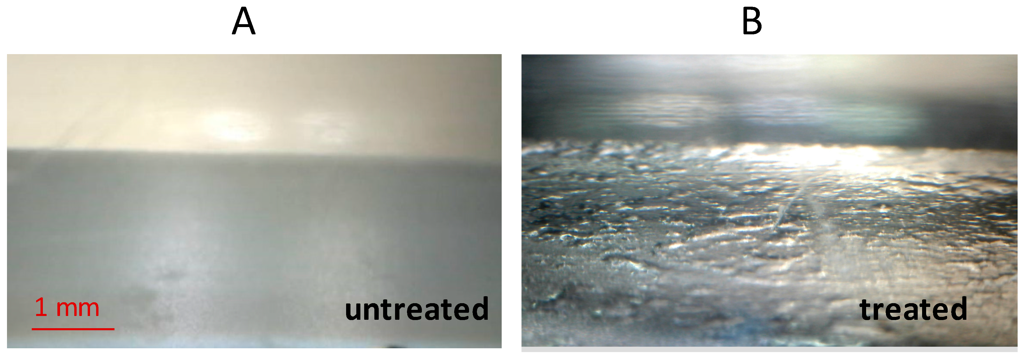
The appearance of these surfaces when submerged by water is shown in the optical photograph of Figure 5. When air is nowadays at the Teflon–h2o interface, the transition of incident visible light through two means with dissimilar refractive index, water and air, gives rise to a specular reflectance, making metallic the appearance of the surface. This is frequently chosen "silver sheen" and some examples are reported in literature [16,22,36,37]. While on the untreated Teflon surface, no shine is observed and the sample appears just like when placed in air, in the case of the treated surface a markedly shiny layer is present. The profile of the air layer seems to form sub-millimetric areas with a deeper thickness, like larger bubbles over an extended bed of air. The shiny layer on this surface is more pronounced than that observed onto other Teflon-structured surfaces that are fifty-fifty more superhydrophobic (higher WCA) than this one [38].
This means that this surface has a stronger ability to favor retention of air confronting wetting events. Since non extremely superhydophobic, it is likely that this ability arises from a certain chapters to trap amounts of air beneath its structures.
This role is probably exerted by the covered voids, which are formed by the bending of the filamentary heads. This concept resembles what is generally ascribed to the surface of the water fern behemothic salvinia Salvinia molesta (refer to Figure ii for comparing), where eggbeaters-like structures act every bit reservoir of air underwater, though the shape and the size scale is much dissimilar (bigger in the case of Salvinia).
It has been observed that Salvinia can stay dry out for several days when placed underwater, though it is non particularly superhydrophobic [23]. From the microscopy images in Figure 2 information technology can be appreciated that for plasma-treated samples the distance betwixt the vertical cusps (pillars)
is of the order of micron units (1.5 µm is the measured mean), the distance between filaments, instead, is of the social club of tens nanometers (
µm). Overpressure in the liquid due to several causes (capillary pressure, impact dynamics, hydrostatic pressure) may lead the water to fill the inter-pillar spaces, but a much higher pressure would be necessary to likewise make full the cavities beneath the filaments. Indeed, given that the pressure
to make full a cavity scales like
[28] it can be calculated that the pressure to penetrate beneath the filaments structure is 100 times that necessary to invade the inter-pillar spaces.
3.4. Drag Variation on Teflon Sphere Falling in Water
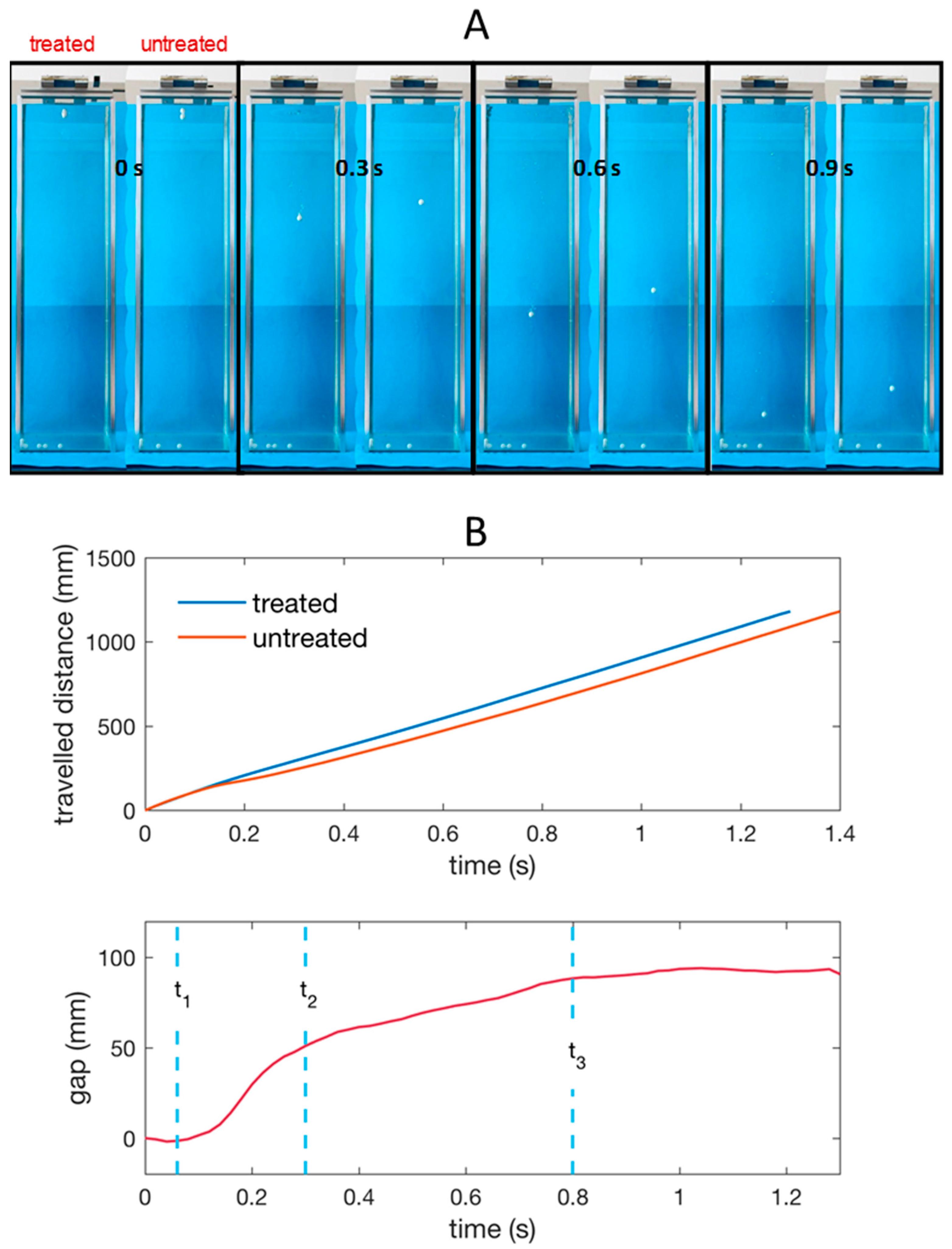
In Figure 6 we show some frames of the spheres' autumn by reporting the treated and the untreated one grabbed at unlike instants later on the first (water entry). The spheres were released from a distance of 55 mm from the h2o surface, so the velocity of the sphere entry (impact) in water is well-nigh one g/south.
Information technology can be noted that the superhydrophobic sphere gets ahead with respect to the untreated one since the starting time trait and holds the vantage until the finish of the fall.
The time interval between the water entry and the spheres impact with the bottom of the tank is
for the untreated sphere and
for the treated sphere, leading to an average velocity calculated as
of
for the untreated and
for the treated sphere (
).
A rough comparison of the performance of the treated and untreated spheres is accomplished considering the ratio of the boilerplate velocities squared, that, in the Reynolds government of the experiment (upwards to
) equals the changed ratio of the average drag coefficients
.
Other authors [21], testing glass spheres coated with metal-oxide particles in a polymer matrix, or investigating acrylic spheres coated with Granger's Gore-Tex [19], reported similar results.
However, we note that the mean velocity related to the whole liquid depth gives merely partial information since a not-uniform variation of the relative position of the spheres is observed along the path. Indeed, Effigy 6B shows the divergence (gap) between the vertical coordinates z (depth nether water gratis surface) of the two spheres vs time. Very small-scale deviations from this bend have been observed (in the first trait curves fully overlap and in the stop deviate at most of four percent) on the three repetitions conducted. After a short time
, the depth is equal for the 2 spheres. In Figure 7 information technology is shown that at the end of this first fourth dimension interval the treated sphere has generated an air cavity, which is completely absent on the untreated sphere. At
the air cavity is sealing on the top and separating from liquid-free surface.
Such behavior of bodies with superhydrophobic coatings is reported in works focused on dynamics of their touch on with the liquid [39,xl].
The air volume adheres to the treated sphere, which, in the subsequent phase from
to
, falls enclosed in a sort of spindle-shaped "air capsule". This miracle is not observed on the untreated sphere, which is unable to retain air in whatsoever course. In this second fourth dimension interval, from
to
, (Figure 6) one tin detect that the treated sphere overcomes the untreated sphere very quickly, meaning that the overall drag force on the treated sphere is much less then on the untreated 1 in this phase.
Indeed, if ane considers that in the treated sphere the upward forcefulness due to buoyancy is increased because of the volume of the retained air, the increased falling down velocity reveals that the drag has been reduced, well across compensation of the buoyancy issue. At time
the treated sphere starts losing the air spindle (Figure 7); air bubbles detach and move upwards and the volume of the air capsule gradually decreases. No alter is visible on the surface of the untreated sphere. Effigy 6 (lesser) shows that in this second phase the difference of depth between the two spheres changes less steeply, pregnant that the relative velocity is decreasing. At time
the treated sphere seems to lose the air capsule, or at to the lowest degree the macroscopic portion (Figure 7). Afterwards, the gap does not change anymore, indicating that the velocity of the two spheres is the aforementioned. We have besides calculated that the velocity in this phase is almost constant for both the spheres (terminal velocity
) and equals 0.91 m/south. The velocity resulting from balancing gravity, buoyancy and drag in steady-state conditions was calculated by solving the falling sphere dynamics equation, considering a Reynolds dependent drag coefficient as previously reported [41]. We obtain
with
.
Thus, this superhydrophobic treatment has substantially reduced the drag in that stage of the sphere autumn when the spindle-shaped air sheathing is well attached to the surface. Indeed, the ratio
restricted to the period 0–800 ms equals 0.77, much lower than that extended to the whole path in a higher place reported.
In agreement with previous predictions [42], in the Reynolds regime of our experiments, a sufficiently thick air layer can change the separation points and the wake cantankerous exclusive area (spindle shape), thus modifying the overall drag substantially.
four. Conclusions
The surface of Teflon can be modified with a single step plasma etching process generating micrometric cusps with nanosized filaments structures having a chemical composition like to pristine Teflon. This modification results in considerably different wetting effects compared to untreated cloth both in air and underwater.
In summary, nosotros take shown that:
- (i)
-
Modified plane Teflon in ambience air repels impacting droplets at high velocity by promoting a full detachment of the liquid in a time as low as previously observed only on heated solids;
- (two)
-
When placed underwater, a shiny picture show is observed on the treated surface, indicating the formation of a continuous air layer between the solid and the liquid;
- (3)
-
The above-mentioned performances are more pronounced on this surface than on other previously shown textured surfaces with higher water contact bending, indicating a relatively higher retaining chapters though a relatively lower superhydrophobicity. These results recall a wetting effect which is similar to that of the behemothic salvinia leaf, which has a high air memory ability though not being particularly superhydrophobic. This may be correlated to the morphology generated by the plasma etching process, similar to the eggbeaters structures on that leaf, both characterized by pillars bearing a curved characteristic on the top, hiding, this way, the lesser function of the surface cavities.
- (iv)
-
Teflon spheres modified under the same conditions present a similar texture; when falling into water (laminar conditions) these samples show a college hateful velocity than the pristine ones. This effect slightly decreases in time (i.e., along the autumn), with a rate which appears to exist correlated with depletion of an "air spindle" continued with the superhydrophobic sphere.
Time to come experiments will be devoted to a more powerful imaging of the air plastron in gild to yield a detailed quantitative analysis of the correlation between the sphere motion (elevate resistance) and air plastron status. Furthermore, spheres made of different density and different diameter are beingness planned to be tested in order to investigate different flow regime weather.
Acknowledgments
Rosa Di Mundo gratefully acknowledges the Futurity in Research Programme of the Apulia Region (Fondo di Sviluppo due east Coesione 2007–2013—APQ Ricerca Regione Puglia "Programma regionale a sostegno della specializzazione intelligente e della sostenibilità sociale ed ambientale") for the contract "low friction materials for water vehicles". Francesco Ancona is warmly acknowledged for the support in camera setting and recording. Antonio Pierro and Corrado Altomare are acknowledged for the help in water fall experiment set-up.
Author Contributions
Rosa Di Mundo conceived and designed the experiments, performed most of the experiments, analyzed the data and wrote the paper; Francesco Bottiglione contributed to experiments and data analysis; Fabio Palumbo performed the plasma modification and chemical characterization; Michele Notarnicola and Giuseppe Pascazio contributed to assay and interpretation.
Conflicts of Interest
The authors declare no conflict of involvement.
References
- Wenzel, R.N. Surface roughness and contact angle. J. Phys. Chem. 1949, 53, 1466–1470. [Google Scholar] [CrossRef]
- Cassie, A.B.D.; Baxter, S. Wettability of porous surface. Trans. Faraday Soc. 1944, 40, 546–551. [Google Scholar] [CrossRef]
- Barthlott, Due west.; Ehler, N. Raster-Elektronenmikroskopie der Epidermis-Oberflächen von Spermatophyten; Tropische und subtropische Pflanzenwelt; Akademie der Wiss. u.d. Literatur: Mainz, Germany, 1977; pp. 19–110. [Google Scholar]
- Drelich, J.; Marmur, A. Physics and applications of superhydrophobic and superhydrophilic surfaces and coatings. Surface Innov. 2014, two, 211–227. [Google Scholar] [CrossRef]
- Gogolides, E.; Ellinas, K.; Tserepi, A. Hierarchical micro and nano-structured, hydrophilic, superhydrophobic and superoleophobic surfaces incorporated in microfluidics, microarrays and lab on chip microsystems. Microelectron. Eng. 2015, 132, 135–155. [Google Scholar] [CrossRef]
- Quéré, D. Non-sticking drops. Rep. Prog. Phys. 2005, 68, 2495–2532. [Google Scholar] [CrossRef]
- Richard, D.; Clanet, C.; Quéré, D. Contact time of a bouncing droplet. Nature 2002, 417, 811–820. [Google Scholar] [CrossRef] [PubMed]
- Richard, D.; Quéré, D. Bouncing water drops. Europhys. Lett. 2000, 50, 769–775. [Google Scholar] [CrossRef]
- Bartolo, D.; Bouamrirene, F.; Verneuil, É.; Buguin, A.; Silberzan, P.; Moulinet, S. Bouncing or glutinous droplets: Impalement transitions on superhydrophobic micropatterned surfaces. Europhys. Lett. 2006, 74, 299–305. [Google Scholar] [CrossRef]
- Reyssat, M.; Pépin, A.; Marty, F.; Chen, Y.; Quéré, D. Bouncing Transitions on microtextured materials. Europhys. Lett. 2006, 74, 306–312. [Google Scholar] [CrossRef]
- Wu, Y.; Saito, N.; Nae, F.A.; Inoue, Y.; Takai, O. Water aerosol interaction with super-hydrophobic surfaces. Surf. Sci. 2006, 600, 3710–3714. [Google Scholar] [CrossRef]
- Rioboo, R.; Voué, M.; Vaillant, A.; De Conick, J. Drop Touch on Porous Superhydrophobic Polymer Surfaces. Langmuir 2008, 24, 14074–14077. [Google Scholar] [CrossRef] [PubMed]
- Brunet, P.; Lapierre, F.; Thomy, 5.; Coffinier, Y.; Boukherroub, R. Extreme Resistance of Superhydrophobic Surfaces to Impalement: Reversible Electrowetting Related to the Impacting/Bouncing Drop Test. Langmuir 2008, 24, 11203–11208. [Google Scholar] [CrossRef] [PubMed]
- Li, X.; Ma, 10.; Lan, Z. Dynamic Behavior of the Water Droplet Touch on a Textured Hydrophobic/Superhydrophobic Surface: The Effect of the Remaining Liquid Film Arising on the Pillars Tops on the Contact Time. Langmuir 2010, 26, 4831–4838. [Google Scholar] [CrossRef] [PubMed]
- Gao, X.; Jiang, L. Water-Repellent Legs of Water Strider. Nature 2004, 432, 36. [Google Scholar] [CrossRef] [PubMed]
- Su, B.; Li, M.; Lu, Q. Toward Understanding Whether Superhydrophobic Surfaces Can Really Decrease Fluidic Friction Drag. Langmuir 2010, 26, 6048–6052. [Google Scholar] [CrossRef] [PubMed]
- Shi, F.; Niu, J.; Liu, J.; Liu, F.; Wang, Z.; Feng, Q.X.; Zhang, X.; Shi, F. Towards Understanding Why a Superhydrophobic Coating Is Needed by Water Striders. Adv. Mater. 2007, 19, 2257–2261. [Google Scholar] [CrossRef]
- Cheng, Thousand.; Zhang, Due south.; Dong, H.; Han, S.; Wei, H.; Shi, F. Improving the durability of a elevate-reducing nanocoating by enhancing its mechanical Stability. ACS Appl. Mater. Interfaces 2015, seven, 4275–4282. [Google Scholar] [CrossRef] [PubMed]
- McHale, G.; Shirtcliffe, N.J.; Evans, C.R.; Newton, One thousand.I. Terminal velocity and drag reduction measurements on superhydrophobic spheres. Appl. Phys. Lett. 2009, 94, 064104. [Google Scholar] [CrossRef]
- Zhang, S.; Ouyang, X.; Li, J.; Gao, S.; Han, Southward.; Liu, L.; Wei, H. Underwater drag-reducing result of superhydrophobic submarine model Zhang. Langmuir 2015, 31, 587–593. [Google Scholar] [CrossRef] [PubMed]
- Brassard, J.-D.; Sarkar, D.Thousand.; Perron, J. Studies of drag on the nanocomposite superhydrophobic surfaces. Appl. Surf. Sci. 2015, 324, 525–531. [Google Scholar] [CrossRef]
- Kavalenka, G.North.; Vüllers, F.; Lischker, S.; Zeiger, C.; Hopf, A.; Röhrig, Grand.; Rapp, B.; Worgull, Due east.; Hölscher, H. Bioinspired Air-Retaining Nanofur for Elevate Reduction. ACS Appl. Mater. Interfaces 2015, 7, 10651–10655. [Google Scholar] [CrossRef] [PubMed]
- Barthlott, W.; Schimmel, T.; Wiersch, S.; Koch, K.; Brede, M.; Barczewski, Thousand.; Walheim, S.; Weis, A.; Kaltenmaier, A.; Leder, A.; et al. The Salvinia Paradox: Superhydrophobic Surfaces with Hydrophilic Pins for Air Retentiveness under Water. Adv. Mater. 2010, 22, 2325–2328. [Google Scholar] [CrossRef] [PubMed]
- Di Mundo, R.; Palumbo, F.; d'Agostino, R. Nanotexturing of Polystyrene Surface in Fluorocarbon Plasmas: From Sticky to Slippery Superhydrophobicity. Langmuir 2008, 24, 5044–5051. [Google Scholar] [CrossRef] [PubMed]
- Di Mundo, R.; Bottiglione, F.; Carbone, G. Cassie land robustness of plasma generated randomly nano-rough surfaces. Appl. Surf. Sci. 2014, 316, 324–332. [Google Scholar] [CrossRef]
- Di Mundo, R.; Troia, G.; Palumbo, F.; d'Agostino, R. Nano-texturing of Transparent Polymers with Plasma Carving: Tailoring Topography for a Depression Reflectivity. Plasma Proc. Polym. 2012, 9, 947–954. [Google Scholar] [CrossRef]
- Vocal, D.; Daniello, R.J.; Rothstein, J.P. Drag reduction using superhydrophobic sanded Teflon surfaces. Exp. Fluids 2014, 55, 1783. [Google Scholar] [CrossRef]
- Di Mundo, R.; Bottiglione, F.; Palumbo, F.; Favia, P.; Carbone, G. Sphere-on-cone microstructures on Teflon surface: Repulsive beliefs confronting impacting water droplets. Mater. Des. 2016, 92, 1052–1061. [Google Scholar] [CrossRef]
- Schneider, C.A.; Rasband, W.S.; Eliceiri, M.W. NIH Paradigm to ImageJ: 25 years of image analysis. Nat. Methods 2012, nine, 671–675. [Google Scholar] [CrossRef] [PubMed]
- Open Source Physics. Bachelor online: http://www.opensourcephysics.org/ (accessed on 21 January 2017).
- Mic Julien, Republic Scientific and Industrial Research Organization, Bugwood.org. Available online: http://www.insectimages.org/browse/detail.cfm?imgnum=0002107#collapseseven (accessed on 21 January 2017).
- Wildeman, S.; Sunday, C.; Lohse, D. On the spreading of impacting drops. J. Fluid Mech. 2016, 805, 636–655. [Google Scholar] [CrossRef]
- Ramachandran, R.; Sobolev, Yard.; Nosonovsky, K. Dynamics of Droplet Bear on on Hydrophobic/Icephobic Concrete with the Potential for Superhydrophobicity. Langmuir 2015, 31, 1437–1444. [Google Scholar] [CrossRef] [PubMed]
- Bird, C.; Dhiman, R.; Kwon, H.-Grand.; Varanasi, K.G. Reducing the contact time of a billowy drib. Nature 2013, 503, 385–388. [Google Scholar] [CrossRef] [PubMed]
- Shen, Y.; Tao, J.; Tao, H.; Chen, S.; Pan, L.; Wang, T. Budgeted the theoretical contact time of a bouncing droplet on the rational macrostructured superhydrophobic surfaces. Appl. Phys. Lett. 2015, 107, 111604-ane–111604-4. [Google Scholar] [CrossRef]
- Sheng, X.; Zhang, J. Air layer on superhydrophobic surface underwater. Colloids Surf. A 2011, 377, 374–378. [Google Scholar] [CrossRef]
- Poetes, R.; Holtzmann, Thou.; Franze, K.; Steiner, U. Metastable Underwater Superhydrophobicity. Phys. Rev. Lett. 2010, 105, 166104-1–166104-4. [Google Scholar] [CrossRef] [PubMed]
- Di Mundo, R.; Bottiglione, F.; Palumbo, F.; Notarnicola, M.; Carbone, G. Filamentary superhydrophobic Teflon surfaces: Moderate apparent contact angle only superior air-retaining properties. J. Colloid Interface Sci. 2016, 482, 175–182. [Google Scholar] [CrossRef] [PubMed]
- Aristoff, J.One thousand.; Bush-league, J.W.M. Water entry of small hydrophobic spheres. J. Fluid Mech. 2009, 619, 45–78. [Google Scholar] [CrossRef]
- Aristoff, M.; Truscott, T.T.; Techet, A.H.; Bush, J.W.M. The water entry of decelerating spheres. Phys. Fluids 2010, 22, 032102-one–032102-eight. [Google Scholar] [CrossRef]
- Clift, R.; Grace, J.R.; Weber, M.E. Bubbles, Drops, and Particles; Academic Press: New York, NY, USA, 1978. [Google Scholar]
- McHale, G.; Flynn, R.G.; Newton, G.I. Plastron induced drag reduction and increased skid on a superhydrophobic sphere. Soft Thing 2011, 7, 10100–10107. [Google Scholar] [CrossRef]
Figure 1. Scheme of the electrodic system of the plasma reactor set up for the plasma nano/microtexturing of the Teflon samples. The upper electrode is a shower-head type to allow homogeneous feed gas (O2) admission. Samples are placed on the bottom electrode which is radio-frequency (RF) powered.
Effigy 1. Scheme of the electrodic organization of the plasma reactor set up for the plasma nano/microtexturing of the Teflon samples. The upper electrode is a shower-caput type to allow homogeneous feed gas (Otwo) admission. Samples are placed on the bottom electrode which is radio-frequency (RF) powered.
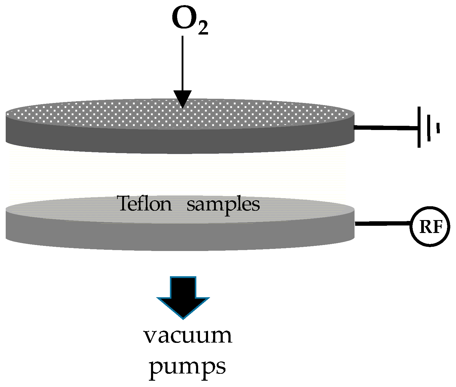
Figure 2. Scanning electron microscopy images of: (A) Untreated Teflon; (B) Surface-textured Teflon sheet at 45° tilt; (C) Surface-textured Teflon sphere at 45° tilt; (D) Micrograph of the behemothic salvinia (Salvinia molesta) surface [31].
Figure 2. Scanning electron microscopy images of: (A) Untreated Teflon; (B) Surface-textured Teflon sheet at 45° tilt; (C) Surface-textured Teflon sphere at 45° tilt; (D) Micrograph of the giant salvinia (Salvinia molesta) surface [31].

Figure 3. X-ray photoelectron spectroscopy (XPS) loftier resolution spectrum of the C1s bespeak for untreated- and plasma-treated Teflon sail. a.u.: Arbitrary units.
Figure 3. 10-ray photoelectron spectroscopy (XPS) high resolution spectrum of the C1s bespeak for untreated- and plasma-treated Teflon sheet. a.u.: Arbitrary units.
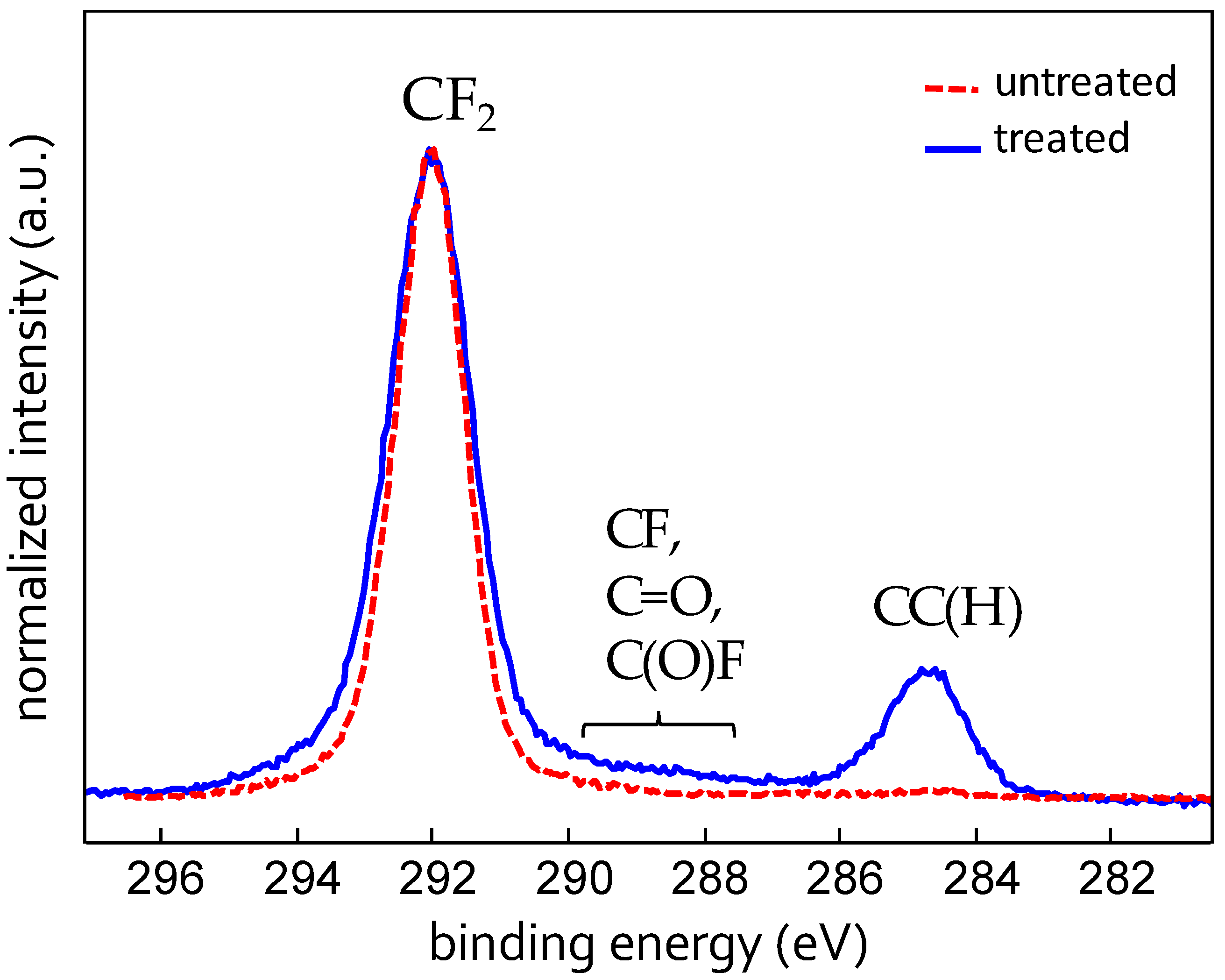
Figure iv. Drop impact on untreated and plasma treated plane Teflon: (A) Snapshots of a 5 µL water drib impacting onto the surfaces grabbed at the same times counted from the frame (0 ms) before the first contact; (B) Measured length of the surface-drop contact during the whole sequence.
Effigy four. Drib impact on untreated and plasma treated plane Teflon: (A) Snapshots of a 5 µL h2o drop impacting onto the surfaces grabbed at the aforementioned times counted from the frame (0 ms) before the first contact; (B) Measured length of the surface-driblet contact during the whole sequence.

Figure 5. Underwater optical microscopy images of notwithstanding (A) untreated and (B) treated Teflon. Samples are fixed to the ground of a transparent box filled with i cm deep water.
Effigy 5. Underwater optical microscopy images of yet (A) untreated and (B) treated Teflon. Samples are stock-still to the ground of a transparent box filled with 1 cm deep water.
Effigy 6. (A) Snapshots of the untreated and treated Teflon spheres falling into the water tank recorded at unlike instants after the get-go (water entry); (B) Vertical coordinate z (depth travelled under the water free surface) of the untreated and treated sphere and respective gap vs fourth dimension. The times tone, t2, and t3 are those corresponding to the images in Figure seven.
Figure six. (A) Snapshots of the untreated and treated Teflon spheres falling into the water tank recorded at different instants after the kickoff (h2o entry); (B) Vertical coordinate z (depth travelled nether the water costless surface) of the untreated and treated sphere and corresponding gap vs fourth dimension. The times t1, tii, and tiii are those respective to the images in Figure 7.
Effigy 7. High magnification images of the spheres falling in the tanks at some representative times (t1, ttwo, and t3 shown in Figure 6 diagrams).
Figure 7. High magnification images of the spheres falling in the tanks at some representative times (t1, tii, and tiii shown in Figure half dozen diagrams).

Table ane. 10-ray photoelectron spectroscopy (XPS) atomic percent and dynamic water contact angle (WCA) values of the untreated and the plasma-modified Teflon samples.
| Teflon Surface | C (%) | F (%) | O (%) | Fe (%) | Adv. WCA (°) | Rec. WCA (°) |
|---|---|---|---|---|---|---|
| Untreated | 33 | 66 | 1 | - | 125 | 94 |
| Treated | 33 | 58 | four | 4 | 162 | 160 |
© 2017 by the authors; licensee MDPI, Basel, Switzerland. This commodity is an open up access article distributed under the terms and weather condition of the Creative Commons Attribution (CC BY) license ( http://creativecommons.org/licenses/by/4.0/).
Source: https://www.mdpi.com/2313-7673/2/1/1/htm
0 Response to "How to Read Droplets on Teflon Slides"
Post a Comment